Thread Starter
#1
First things first
DISCLAIMER
Now that we have that out of the way, here is the process:
Things you will need
Steps:
Before doing anything else, disconnect battery negative terminal and wait for 10 minutes. On opening the bonnet, you will see a black rubber grommet at the left corner, just behind the power steering fluid container. The bonnet lock release cable will be routed through this. You will also see a thick rubber padding above the plastic trim, that holds the wipers. On moving this trim, you will see that the plastic trim is screwed down to the body with a Philips head screw. Undo that screw and you should see another rubber grommet on the body, through which the bonnet lock release cable will enter the cabin. With a screw driver, make holes into both grommets.
Now pass through a thick (10 gauge) wire or a GI wire from the engine bay, though the grommets into the car. This will eventually pop out inside the car from behind the fuse box. Take 4 lengths of the 24/26 AWG wire, strip the insulation approx 1 inch and tie to the wire you just inserted. Make sure you do not have any sharp edges that might snag somewhere. Now start pulling the thick wire you inserted back into the engine bay, till all the four wires come out. Cut off the thick wire.
Now that we have routed 4 wires to the engine bay, we have to connect them to the ECU. Here is a short video of how to open the ECU connector.
Once you have that open, detach the semicircular lid on top, to expose the wires connected to the ECU.
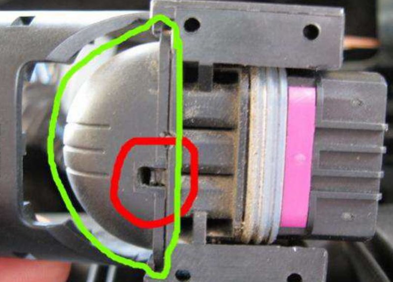
Now turn the connector over and remove the purple tab that locks the pins in the ECU.
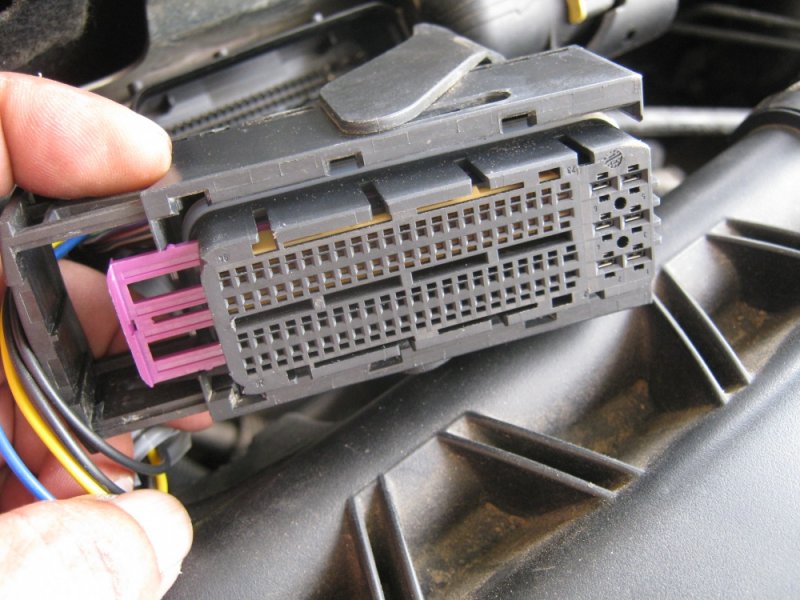
Now, crimp and terminate the four wires we have with MQS connectors. One wire already plugged in. So you are seeing only three wires.
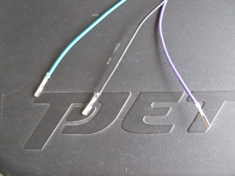
All four wires connected to the plug. The MQS connecters go in only one way and lock with a reassuring click.
Once inserted into the ECU, they will look like this:

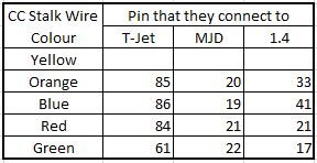
Please make notes of which wire is in which pin.
The pins to connect to, will depend on the variant of Linea you are doing the installation on:
For the T-Jet
Pin 61
Pin 84
Pin 85
Pin 86
For the 1.3 MJD
Pin 19
Pin 20
Pin 21
Pin 22
For the 1.4 8V
Pin 17
Pin 21
Pin 33
Pin 41
At this point, make a note of which colour wire is connected to which pin. Now that we are done with wiring to the ECU, it is time to finish the end inside the car.
Ground work, before we start the connection inside the car.
The Alfa 147 stalk that I bought looked like this:
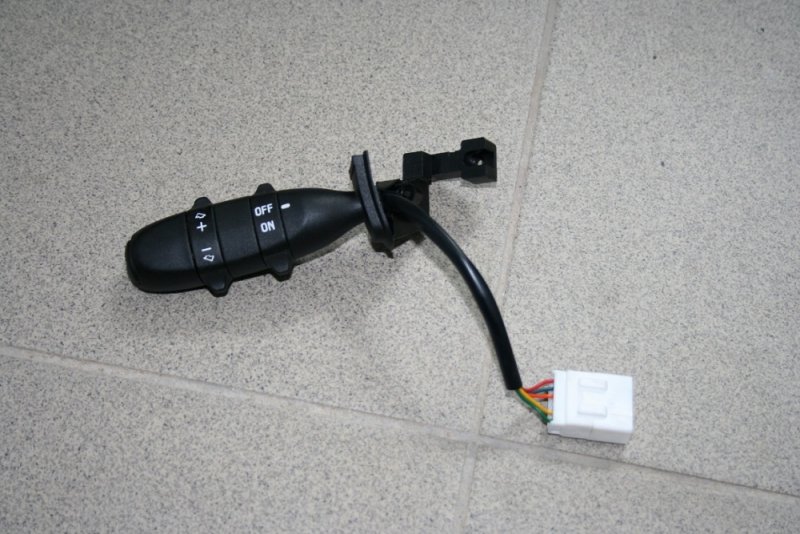
The part that is meant for fitting on the steering column, does not fit the Linea (It is meant for the Alfa, remember?). So that part needs to be cut off

If you are able to find a suitable female connector for the stalk, you can skip this step. I have used 3 two way connectors. You can use a single 5 way connector as well.

Now take the end of the four wires we connected to the ECU and crimp and connect the other half of the two way connectors to them. This is where, our notes made when connecting to the ECU come in handy. The Alfa stalk has 5 wires. The connection need to be made in the following way.
Now take off the lower portion of the steering column shroud. It is held up by 4 allen screws (3 mm) and 3 Philips head screws. 2 of the Philips head screws are hidden beneath the steering wheel tilt adjustment lever, so releasing that lever and bringing the steering to the lowest position first is necessary. Once you have the lower shroud off, take off the oblong piece of plastic that extends from the headlight / turn indicator lever. Now use your imagination to fit the modified stalk to this piece. Doing this step, before connecting replacement connectors to the stalk wires will help in getting a better fitment. I did not think of it and ended up with a rather awkward fit.

You might have noticed that we still have the yellow wire on the CC stalk, not connected to anything. We need to provide a +12 V source to this. I used the fuse marked "Sub woofer" in my car. Any source - direct from battery, splicing into another wire or even from the cigarette lighter socket, though it may not look very elegant. At this point, if you put everything back together, you should have a working cruise control in your car. However, you may not have an indicator light in the console or message in the MID.
The following steps will enable this functionality:
Connect the ELM 327 to the OBD port (located in the fuse box under the steering wheel), connect to laptop, turn key to MAR and fire up FIATEcuScan / MultiECUScan software.
Choose your vehicle and connect to Dashboard Module, Marelli Instrument Panel, go to the tab that reads "Actuators", scroll down to Cruise Control and click Execute. A small green light should come on in the bottom left of the Console.

This is just to ensure that you have the LED in your dashboard console. Now disconnect from the module, go back to the main menu and select STILO 1.9 JTD as your car and connect to Body - CAN Setup / PROXI Alignment Procedure.

You will get this pop up

Click Y, select the adjustments tab. The very first option should be Cruise Control Light. Select that and click Execute. You will get another pop up. Choose enabled and click OK. From the same screen select PROXI ALIGNMENT PROCEDURE - the last item and execute. You will get 2 pop ups, one asking you to read all the notes and another as pictured earlier, saying the vehicle is properly configured. Click Y on both, let the process finish.

Now, if you turn off the car, wait for 5 seconds and then turn back to MAR and turn the CC stalk ON, you should see this:


Now you are all set to go on that highway drive and cruise along . As an added bonus, you will also notice that from the second time onwards (i.e. after having started the engine at least once post installation), every time you get in the car and turn the key to MAR, in addition to all other check lights, the CC light will also come on for 2 seconds.
The Cruise Control works exactly as described in the Europe Manual of the Linea.


My observations after installing and using this feature :
Thanks for reading.
Rajan
DISCLAIMER
- If you try this and render your car inoperable / burnt to ashes / worthless piece of junk - you are responsible, I am not
- If your car is in warranty and you do not want to lose it, stop reading now
- This post is exclusively for Linea Owners.
- I have only tested this on the Old T-Jet (2010 model). I have no idea if it works in other models
Now that we have that out of the way, here is the process:
Things you will need
- 24 - 26 AWG automotive grade wire - 2 meters each of 5 different colours. If you do not get different colours, you can use the same colour, but mark each end with a different coloured insulation tape after cutting to size
- 2 mts corrugated tube
- Alfa 147 cruise control stalk - I used this. Other possibilities exist.
- Set of 5 (5 male & 5 female) - Round pin type solder-less wire crimp terminals
- 3 sets of two way connectors
- 4 numbers TE MQS connectors - Part number 968220-1
- Licensed copy of FIATECUScan / MultiECUScan software - I have version 3.4.2 of FES and it works great.
- ELM327 USB ECU OBDII scanner
- Basic tools - wire stripper, crimping tool, pliers, screwdriver set, etc.
Steps:
Before doing anything else, disconnect battery negative terminal and wait for 10 minutes. On opening the bonnet, you will see a black rubber grommet at the left corner, just behind the power steering fluid container. The bonnet lock release cable will be routed through this. You will also see a thick rubber padding above the plastic trim, that holds the wipers. On moving this trim, you will see that the plastic trim is screwed down to the body with a Philips head screw. Undo that screw and you should see another rubber grommet on the body, through which the bonnet lock release cable will enter the cabin. With a screw driver, make holes into both grommets.
Now pass through a thick (10 gauge) wire or a GI wire from the engine bay, though the grommets into the car. This will eventually pop out inside the car from behind the fuse box. Take 4 lengths of the 24/26 AWG wire, strip the insulation approx 1 inch and tie to the wire you just inserted. Make sure you do not have any sharp edges that might snag somewhere. Now start pulling the thick wire you inserted back into the engine bay, till all the four wires come out. Cut off the thick wire.
Now that we have routed 4 wires to the engine bay, we have to connect them to the ECU. Here is a short video of how to open the ECU connector.
Once you have that open, detach the semicircular lid on top, to expose the wires connected to the ECU.
Now turn the connector over and remove the purple tab that locks the pins in the ECU.
Now, crimp and terminate the four wires we have with MQS connectors. One wire already plugged in. So you are seeing only three wires.
All four wires connected to the plug. The MQS connecters go in only one way and lock with a reassuring click.
Once inserted into the ECU, they will look like this:
Please make notes of which wire is in which pin.
The pins to connect to, will depend on the variant of Linea you are doing the installation on:
For the T-Jet
Pin 61
Pin 84
Pin 85
Pin 86
For the 1.3 MJD
Pin 19
Pin 20
Pin 21
Pin 22
For the 1.4 8V
Pin 17
Pin 21
Pin 33
Pin 41
At this point, make a note of which colour wire is connected to which pin. Now that we are done with wiring to the ECU, it is time to finish the end inside the car.
Ground work, before we start the connection inside the car.
The Alfa 147 stalk that I bought looked like this:
The part that is meant for fitting on the steering column, does not fit the Linea (It is meant for the Alfa, remember?). So that part needs to be cut off
If you are able to find a suitable female connector for the stalk, you can skip this step. I have used 3 two way connectors. You can use a single 5 way connector as well.
Now take the end of the four wires we connected to the ECU and crimp and connect the other half of the two way connectors to them. This is where, our notes made when connecting to the ECU come in handy. The Alfa stalk has 5 wires. The connection need to be made in the following way.
Now take off the lower portion of the steering column shroud. It is held up by 4 allen screws (3 mm) and 3 Philips head screws. 2 of the Philips head screws are hidden beneath the steering wheel tilt adjustment lever, so releasing that lever and bringing the steering to the lowest position first is necessary. Once you have the lower shroud off, take off the oblong piece of plastic that extends from the headlight / turn indicator lever. Now use your imagination to fit the modified stalk to this piece. Doing this step, before connecting replacement connectors to the stalk wires will help in getting a better fitment. I did not think of it and ended up with a rather awkward fit.
You might have noticed that we still have the yellow wire on the CC stalk, not connected to anything. We need to provide a +12 V source to this. I used the fuse marked "Sub woofer" in my car. Any source - direct from battery, splicing into another wire or even from the cigarette lighter socket, though it may not look very elegant. At this point, if you put everything back together, you should have a working cruise control in your car. However, you may not have an indicator light in the console or message in the MID.
The following steps will enable this functionality:
Connect the ELM 327 to the OBD port (located in the fuse box under the steering wheel), connect to laptop, turn key to MAR and fire up FIATEcuScan / MultiECUScan software.
Choose your vehicle and connect to Dashboard Module, Marelli Instrument Panel, go to the tab that reads "Actuators", scroll down to Cruise Control and click Execute. A small green light should come on in the bottom left of the Console.
This is just to ensure that you have the LED in your dashboard console. Now disconnect from the module, go back to the main menu and select STILO 1.9 JTD as your car and connect to Body - CAN Setup / PROXI Alignment Procedure.
You will get this pop up
Click Y, select the adjustments tab. The very first option should be Cruise Control Light. Select that and click Execute. You will get another pop up. Choose enabled and click OK. From the same screen select PROXI ALIGNMENT PROCEDURE - the last item and execute. You will get 2 pop ups, one asking you to read all the notes and another as pictured earlier, saying the vehicle is properly configured. Click Y on both, let the process finish.
Now, if you turn off the car, wait for 5 seconds and then turn back to MAR and turn the CC stalk ON, you should see this:
Now you are all set to go on that highway drive and cruise along . As an added bonus, you will also notice that from the second time onwards (i.e. after having started the engine at least once post installation), every time you get in the car and turn the key to MAR, in addition to all other check lights, the CC light will also come on for 2 seconds.
The Cruise Control works exactly as described in the Europe Manual of the Linea.
My observations after installing and using this feature :
- CC is unfit for a MT car is a myth. One just has to remember to slot into 4th / 5th before hitting the RES button. It works even if you are in 2nd, but revs hard to get to the preset speed.
- CC is not fit for Indian roads / traffic is also a myth. You can set any speed, starting from 30 kmph.
- The acceleration when you hit RES is linear and very nice
- I have been using this in the city outskirts and am seeing a 15% improvement in FE
Thanks for reading.
Rajan
![[clap]](https://www.theautomotiveindia.com/forums/images/smilies/Clap.gif "Clap [clap]")