Thread Starter
#1
Hello friends time for yet another DIY!I have been experiencing rough noisy ride on bad roads and my daughter complained that the car made far too much noise ![Smile [:)] [:)]](https://www.theautomotiveindia.com/forums/images/smilies/Smile.gif) .
.
For a while i have been contemplating to replace the lower control arm ball joint as it had been damaged with loss of grease. Since M800 MGP spares of lower ball joint comes as a single unit with the lower control arm ,i chose to replace both sides at the same time as best preventative maintenance.
I have chosen to make slides with pictures for the entire procedure attached in this thread.
The entire procedure took me around 2 hours.
METHOD FOR CONTROL ARM REPLACEMENT
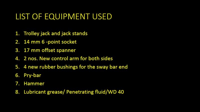
1. The customary jacking up of car and placement of jack stands with rear wheel chocks; douse all the bolts with penetrating fluid WD40 at start of the entire process to sufficiently help in removing the bolts
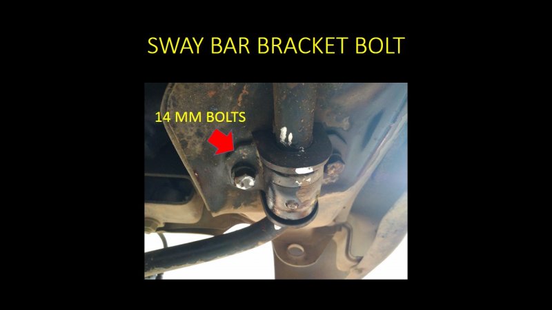
2. For removal of control arm the sway bar needs to be removed first .14mm hex bolts are removed to undo the clamps holding the sway bar; 17 mm castle nut with cotter pin to be undone to remove the sway bar end passing through the control arm.A deep 17 mm socket or a ring spanner is more useful in this situation.
3. Pull the entire sway bar out and replace the rubber bushings after applying a silicon lubricant on the metal. I used white paint to mark the mounting points so that it would align the same way it was removed .
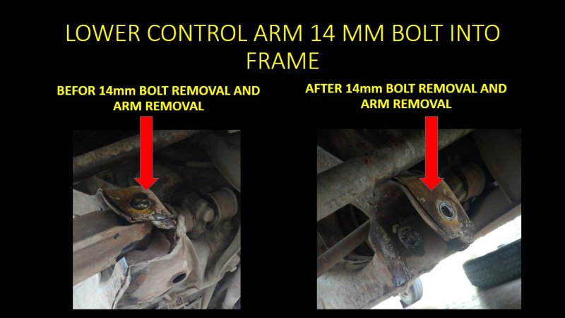
4. Next undo the 14mm bolt holding the control arm on to the frame of the car. Use a longer wrench for extra leverage.
5. Undo the 14 mm pinch bold holding the lower ball joint into the knuckle .Use a hammer and twisting motion to remove the control arm from its seat in the frame and the ball joint from the knuckle.
6. Clean the areas on the frame and knuckle where the new parts go in and needed to be bolted with diesel and WD40.
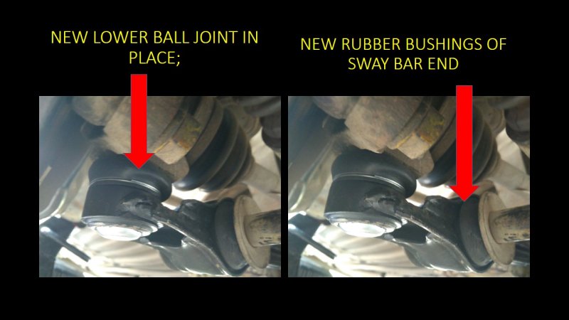
7. Now do the steps in reverse to first seat the control arm end first and push the ball joint into the knuckle and apply the pinch bolt. I used a piece of wood and hammer to knock the control arm into its position .Do the same on both sides .Apply the bolts loosely.
8. Finally seat the sway bar with rubber bushings through the control arm and apply the castle nut with the metal washer. Make sure the entire setup is fully aligned before starting to tighten the bolts. Use a new cotter pin and bend it appropriately.
TORQUE SPECS FOR THE VARIOUS BOLTS
castle nut :65 Nm
Sway bar bushing bracket bolt :43 Nm
Flexible hose to caliper banjo bolt :23 Nm
Ball stud pinch bolt :55Nm
Control arm bolt : 65Nm.
Finish.
lower the car down and then once finally go around tightening all the bolts .Go for a test ride .I must say the car has sufficiently quietened on bumpy roads and takes bumps more easily![Clap [clap] [clap]](https://www.theautomotiveindia.com/forums/images/smilies/Clap.gif) .
.
![Smile [:)] [:)]](https://www.theautomotiveindia.com/forums/images/smilies/Smile.gif) .
.For a while i have been contemplating to replace the lower control arm ball joint as it had been damaged with loss of grease. Since M800 MGP spares of lower ball joint comes as a single unit with the lower control arm ,i chose to replace both sides at the same time as best preventative maintenance.
I have chosen to make slides with pictures for the entire procedure attached in this thread.
The entire procedure took me around 2 hours.
METHOD FOR CONTROL ARM REPLACEMENT
1. The customary jacking up of car and placement of jack stands with rear wheel chocks; douse all the bolts with penetrating fluid WD40 at start of the entire process to sufficiently help in removing the bolts
2. For removal of control arm the sway bar needs to be removed first .14mm hex bolts are removed to undo the clamps holding the sway bar; 17 mm castle nut with cotter pin to be undone to remove the sway bar end passing through the control arm.A deep 17 mm socket or a ring spanner is more useful in this situation.
3. Pull the entire sway bar out and replace the rubber bushings after applying a silicon lubricant on the metal. I used white paint to mark the mounting points so that it would align the same way it was removed .
4. Next undo the 14mm bolt holding the control arm on to the frame of the car. Use a longer wrench for extra leverage.
5. Undo the 14 mm pinch bold holding the lower ball joint into the knuckle .Use a hammer and twisting motion to remove the control arm from its seat in the frame and the ball joint from the knuckle.
6. Clean the areas on the frame and knuckle where the new parts go in and needed to be bolted with diesel and WD40.
7. Now do the steps in reverse to first seat the control arm end first and push the ball joint into the knuckle and apply the pinch bolt. I used a piece of wood and hammer to knock the control arm into its position .Do the same on both sides .Apply the bolts loosely.
8. Finally seat the sway bar with rubber bushings through the control arm and apply the castle nut with the metal washer. Make sure the entire setup is fully aligned before starting to tighten the bolts. Use a new cotter pin and bend it appropriately.
TORQUE SPECS FOR THE VARIOUS BOLTS
castle nut :65 Nm
Sway bar bushing bracket bolt :43 Nm
Flexible hose to caliper banjo bolt :23 Nm
Ball stud pinch bolt :55Nm
Control arm bolt : 65Nm.
Finish.
lower the car down and then once finally go around tightening all the bolts .Go for a test ride .I must say the car has sufficiently quietened on bumpy roads and takes bumps more easily
![Clap [clap] [clap]](https://www.theautomotiveindia.com/forums/images/smilies/Clap.gif) .
.Attachments
-
98.1 KB Views: 192
-
88 KB Views: 224
-
136.3 KB Views: 210
-
139.7 KB Views: 219
-
122.9 KB Views: 196
-
117.3 KB Views: 231
-
99 KB Views: 205


![Wink [;)] [;)]](https://www.theautomotiveindia.com/forums/images/smilies/Wink.gif) the car is more silent now especially with sharp edged ditches and the ride is more firm now .
the car is more silent now especially with sharp edged ditches and the ride is more firm now .